End Face Grooving
On CNC lathe, when machining end face grooves on the surface of a part, selecting the correct tool is crucial. The radius of the groove will determine the curvature of the tool. Since the groove is arc-shaped, chip removal can become an issue. Chips clogging the groove can lead to blade breakage, creating safety hazards.
1. How to Choose the Right End Face Grooving Tool
1.1 Diameter Range (DAXIN and DAXX)
Select the diameter range (DAXIN and DAXX) for the first cut. Use a tool with the maximum diameter suitable for your groove. Larger diameter tools have less curvature, providing greater rigidity and stability. They also improve chip control.
1.2 Cutting Part Length (CDX)
When machining with a CNC lathe, please use the shortest possible cutting length for maximum stability.
1.3 Tool Width (CW)
A wider tools holder offers higher stiffness and provides greater stability.
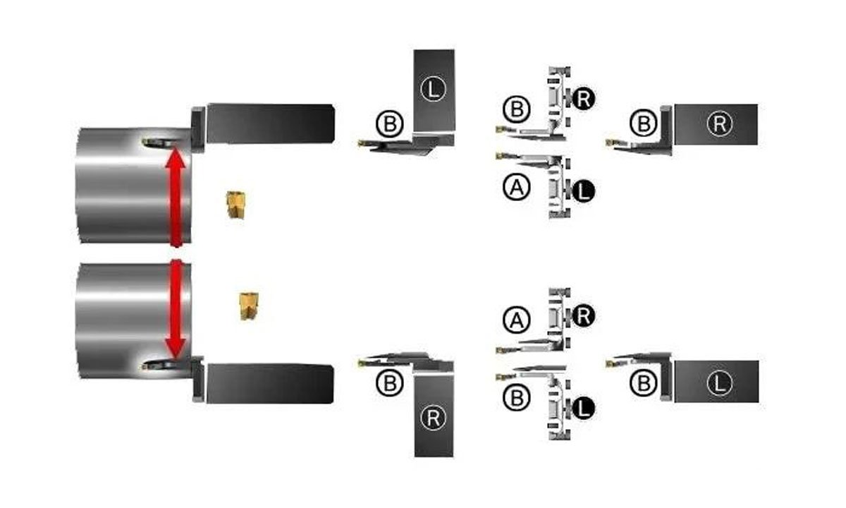
1.4 Tool Direction and Type
Choose the correct tool (Type A or Type B) based on the rotation of the CNC lathe and the workpiece.
1.5 Tool Holder Recommendations
When selecting the right tool holder for end face grooving operations, consider the following:
Tool holder interface selection. Choose modular or integral solutions.
For optimal performance in end face grooving, it is recommended to use tools specifically designed for this operation.
2. How to Choose the Right End Face Grooving Tool for Boring
When machining end face grooves on a part, it is essential to select a suitable blade and tool holder. The tool holder must accommodate the curvature of the groove, so it should be arc-shaped. Chip control is critical in end face grooving: chips should be long enough to avoid getting stuck in the groove but short enough to prevent jamming on the tool or wrapping around the part.
3. End Face Grooving Process
3.1 Rough Machining
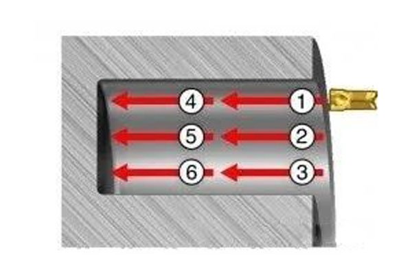
Start with the maximum diameter (1) and then machine inward. This step is best done with continuous cutting to avoid chips getting stuck in the narrow groove. If you want shorter chips, use peck machining or pause during machining. Further cuts (2, 3) should be (0.5~0.8) × blade width. Since chips are easier to remove at this stage, you can increase the feed rate by 30-50%. Typically, you will achieve shorter chips in these steps.
3.2 Deep Cutting
When machining deep grooves (> 25 mm), it is recommended to proceed in two steps:
Machine a groove with 50% depth and the desired width (1, 2, 3).
Machine to the desired depth (4, 5, 6).
3.3 Stepped Cutting
Side turning provides better chip control and chip breaking. Start machining from the maximum diameter towards the center. Do not feed from the shoulder, and leave a step of 0.2 mm (0.008 inches) between each pass. Side turning is more stable than axial feed cutting. Using side turning can avoid vibrations. Note that due to the lower cutting depth, the production efficiency of side turning is lower than that of axial cutting.
3.4 Finishing
Achieving good chip control during finishing is always challenging, especially when machining fillets. It is important to separate the material to be removed by performing three cuts:
The first axial cut is made near the fillet radius at the maximum diameter.
The second cut machines to the fillet radius on the inner diameter.
The third cut completes the inner diameter and the fillet radius.
4.Coolant
In deeper grooves, use the highest possible coolant pressure, up to 80 bar (1,160 psi), to achieve better chip control and chip removal.


