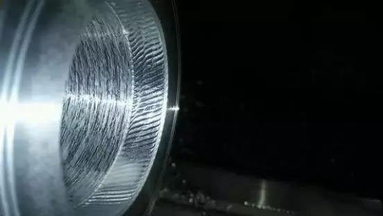
How to solve the problem of tool vibration in machining
When the tool is processing the workpiece, it will generate a component force (Fp) in the radial direction.
When the force is applied, if the tool is not rigid enough, the tool body will deform, and a deviation will be produced in the direction of the force, and there will be a displacement. The tool has a displacement, so the depth of the knife will be smaller, the force will be smaller, and the displacement will be smaller. The generated displacement becomes smaller, and the tool moves in the opposite direction of the force, so that the cutting depth becomes larger, and the cutting becomes larger at the same time.
This is like comparing a tool to a long and thin wooden stick. One end is fixed and the other end is stressed, so the end away from the unfixed end will be deflected and rebound.
In this way, during the machining process, constantly changing cutting forces act on the tool and the workpiece, resulting in vibrations.
Then we can see that there are two directly related factors that generate vibration:
First,the strength of the tool body itself
The strength of the tool body itself is easy to understand, the thicker and shorter it is, the greater the strength.
So if you want to solve the vibration problem in this direction, then make the cutter body shorter and thicker, and it will definitely solve the problem. If the processing length is required, the following issues should also be paid attention to:
1. The protruding length of the steel tool rod is controlled within 3 times the diameter.
2. The protruding length of the heavy metal tool rod is controlled within 6 times the diameter.
3. If it is still longer, use a shock-absorbing tool holder as much as possible.
Second, the size of the cutting force
Cutting force, this is better understood, the smaller the cutting force, the smaller the vibration. So from the perspective of tools, you can choose the right tools from the following two aspects, and the effect will be immediate.
1. Tools with large rake angle and small cutting-edge width
Regarding the width of the cutting edge, many friends said they don’t know, so I won’t explain the specific concept.
The rake angles of the two types of blades in the picture above are 20 degrees and 24 degrees respectively, and the cutting edge widths are 0.27 and 0.12 respectively.
That is to say, the larger the rake angle, the smaller the cutting edge width means the sharper the tool and the smaller the cutting force during the cutting process.
In addition, the cutting edge width of the tool is very important, which directly determines the size of the feed F during programming.
1. Cutting edge angle of tool
During the process of cutting a part, the tool is subjected to two forces, axial and radial cutting force.
For example, as shown in the figure below:
The picture above shows a tool with a leading angle of 45°. The length of the red arrow indicates the magnitude of the force in this direction, that is, the radial force is greater than the axial force.
The picture above shows a tool with a 95° lead angle. The length of the red arrow indicates the magnitude of the force in this direction, that is, the radial force is smaller than the axial force.
That is to say, the size of the tool's leading angle directly determines the size of the radial cutting force. The larger the tool's leading angle, the smaller the cutting force in the radial direction, and the smaller the cutting angle, the greater the cutting force in the radial direction.
The above three common cutting tool angles are: 90°, 75°, 45°. The smaller the entering angle, the greater the radial force, and the greater the tendency of the tool to vibrate.
Well, the above is pure dry goods, and I will share so much, I hope everyone can study and think deeply.


