How to use a double-spindle lathe for polygonal butt jointing?
In modern precision machining, dual-spindle machines have become the industry focus due to their unique design and efficient machining capabilities. Multi-polygon alignment, as an emerging machining technique, demonstrates exceptional processing efficiency and product quality with the support of dual-spindle machines. This article will explore the technical features of dual-spindle multi-polygon alignment solutions and their advantages in practical applications.

What is a Dual-Spindle Multi-Polygon Alignment Solution?
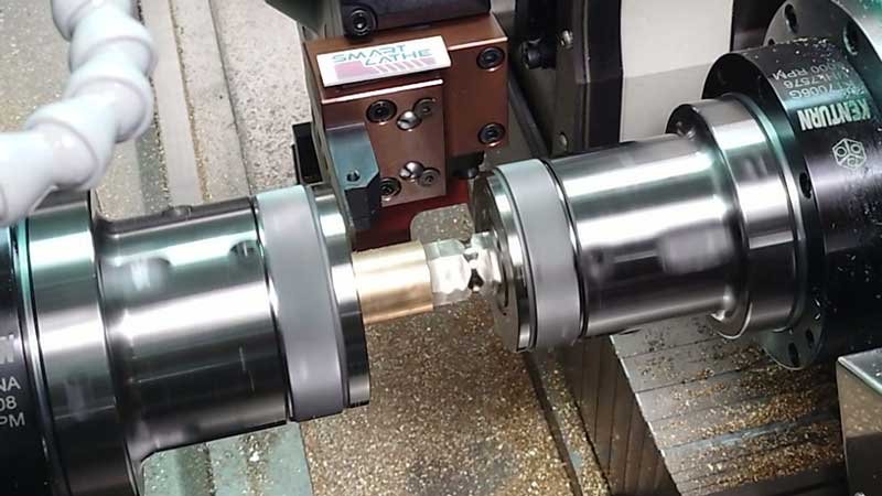
A dual-spindle polygon alignment solution is an advanced machining technique based on dual-spindle CNC lathes. The process involves two alignment methods: static alignment and synchronous rotation alignment. By coordinating the high-speed rotation and precise positioning of two spindles, this technique achieves fast and high-precision machining of polygonal parts. It is widely used in industries such as aerospace, automotive manufacturing, and electronics, meeting the needs of efficient production for complex geometric components.
What is Static Alignment?
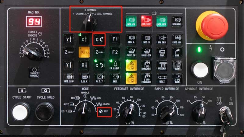
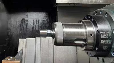
When machining polygonal parts on a dual-spindle CNC lathe, transferring the part from the main spindle to the sub-spindle requires alignment functionality. Static alignment primarily involves using the indexing function to adjust the C-axis of both spindles to suitable angles for part transfer. Static alignment is generally used for material alignment. Below is a demonstration using the DS-4636DTY lathe with Syntec CNC system:
Process Steps:
1. Perform homing for the C-axis of both spindles.
2. Move the sub-spindle to the alignment position.
3. Use the handwheel to adjust the sub-spindle's C-axis angle to the correct alignment position and record the angle.

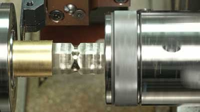
4. Use the handwheel to move the sub-spindle chuck to the part's clamping position.
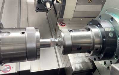
5. The sub-spindle clamps the workpiece, the main spindle releases the chuck, and the sub-spindle pulls out the workpiece and moves to a safe position.
Program Example:
|
$1 |
$2 |
|
G04.1P1 |
G04.1P1 |
|
M19 |
M19 |
|
G0C0 |
G0C30.15 |
|
G04.1P2 |
T45 |
|
M11 |
G0X0 |
|
G04.1P3 |
Z1 |
|
G4X5 |
G98 G1Z-20F500 |
|
M20 |
M10 |
|
M30 |
G4X1 |
|
|
G04.1P2 |
|
|
G04.1P3 |
|
|
G4X1 |
|
|
G1 Z1F500 |
|
|
G0 Z200 |
|
|
X-500 |
|
|
M20 |
|
|
M30 |
What is Dynamic Alignment?
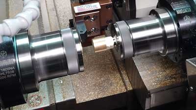
Dynamic alignment is used when transferring a polygonal part from the main spindle to the sub-spindle on a dual-spindle CNC lathe. It uses synchronous rotation commands to rotate both spindles at the same speed for alignment. Below is a demonstration using the DS-4636DTY lathe with Syntec CNC system:
Process Steps:
1. Adjust the sub-spindle's C-axis angle as in static alignment and move the chuck to the clamping position. Open the "Set Shift Angle" page to set the angle.
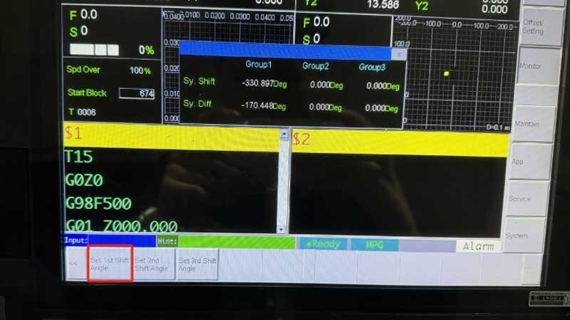
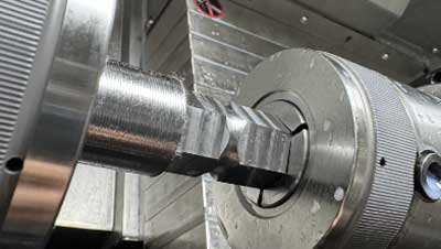
2. Enable synchronous rotation, move to a safe distance, open the chuck, and move to the clamping position.
3. Limit the sub-spindle torque, increase the main spindle speed, cut the workpiece, and retract the sub-spindle to a safe position.
Program Example:
|
$1 |
$2 |
|
G04.1P7 |
G04.1P7 |
|
T0101 |
M4S500 |
|
M40 |
G04.1P1 |
|
M3S200 |
M11 |
|
G4X1 |
T45 |
|
G114.1R0 |
G0X0 |
|
G04.1P1 |
Z10 |
|
G0Z-73.1 |
G98 |
|
Y0 |
G1Z-10F500 |
|
X35 |
M10 |
|
G04.1P2 |
G4X1 |
|
M40 |
M31 |
|
M3S1000 |
G04.1P2 |
|
G99 |
G04.1P3 |
|
G1X-1.5F0.07 |
G98 |
|
G04.1P3 |
G1Z10F500 |
|
G04.1P4 |
G0Z150 |
|
G0Z100 |
X-500 |
|
X300 |
G04.1P4 |
|
G113 |
G04.1P5 |
|
M05 |
M32 |
|
G04.1P5 |
M5 |
|
M9 |
M30 |
|
M30 |
|